Juma Roofing FL2

Posted:
13 May 2016 12:47by HB9FIH
 Viewed 4794 times")
- FL2
Just buid the FL2
Changed with the existing.
- NAR = ok like before (not qualifying now)
- MID = Sig far away, like attenuated
- WID = Sig far away, like attenuated
Checked all components - seems OK.
Is there anything to change in Setup ? or only with newer Firmware ?
I have Firmware 1.20C
Re: Juma Roofing FL2
Posted:
14 May 2016 14:38by 5B4AIY
Hi,
You will find a plot of the frequency responses of both the old and the new filter in another post of mine on this website, and that shows that the new filter is significantly narrower in both the CW and SSB modes compared with the original. To save you having to search for it, I am attaching the document to this post. In addition, the ultimate stop-band attenuation is also much better. From your description, I'm not entirely sure whether you think you have a fault.
Be aware that the roofing filter selection depends upon which mode, CW or SSB is selected. If CW is selected, then the narrow roofing filter is placed in circuit, otherwise in the SSB modes for both USB and LSB, the wide roofing filter is inserted. In either case the mid-band gain of the filter is the same as the original, and both the narrow and wide filters have a gain of unity, there is neither attenuation nor amplification. As a result, no changes in either the firmware or the calibration/setup is required, this is a straight plug-in upgrade.
Please note that the Narrow, Mid, and Wide bandwidth selections apply to the post-detection audio filtering, and have nothing to do with the Narrow or Wide roofing filter bandwidth. The roofing filter bandwidth should more properly be described as a CW or SSB mode bandwidth selection. If you think that you have a problem with the filter, you can of course compare it with the original. Since the S-meter reading is derived from the audio signal, a quick way of checking the filter's insertion gain is to tune in a steady CW carrier, for example from a local signal source, and compare the S-meter reading in the CW and SSB modes of operation. With the same audio frequency beat note in both cases, the same S-meter reading should be obtained. If the signal is severely attenuated then this points to a problem in the filter or the select switch. I would first check with a multi-meter the DC voltage at the pin 7 of IC4-B. As the filter is DC coupled, you should see +5V. If not then check pin 1 of IC4-A. Similarly you should see +5V on pins 1 and 7 of IC3, as well as pins 1 and 7 of IC1 and IC2.
If these voltages are not obtained, then carefully check that all the resistors are properly soldered and that you haven't missed a joint. This is easy to do, and most faults with the transceiver have been as a result of a missed soldered joint rather than a faulty component.
Regards, Adrian, 5B4AIY
Re: Juma Roofing FL2
Posted:
15 May 2016 16:01by HB9FIH
OK Adrian
I check tomorrow, I am a bit tired from:
I made the CQ MIR Contest with JUMA TRX2A and PA100D here from TA3
(I'm in my house in TA3) - and for me successfull, (of course not in front, but ok for me)
Here my report:
http://www.hb9fih.org/?p=p_263&sName=ta ... .-mai-2016Also ARI (Italian) Contest last weekend:
http://www.hb9fih.org/?p=p_262&sName=ta ... 8.mai-2016Gruss Erich
Re: Juma Roofing FL2 - resolved
Posted:
16 May 2016 20:34by HB9FIH
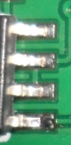
- this ones...
- FL2-X.jpg (41.02 KiB) Viewed 4770 times
hmm I ashamed......
3 pins of first IC in SSB part...seems like soldered - shining wonderfull but.......
TNX
Greetings from Turkey -just had a QSO with JA on 30m - with JUMA and new Filter